February 3, 2023
Pogo pin hardware define
Pins 6, 7, 13, 14 are turned OFF by default. These can be turned on via SDK.
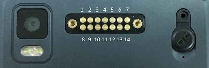
| 1 | GND | Ground PIN | 8 | UART_RX | 1.8V UART RXD |
| 2 | GND | Ground PIN | 9 | UART_TX | 1.8V UART TXD |
| 3 | GND | Ground PIN | 10 | GPIO_1 | 1.8V GPIO 1 |
| 4 | GND | Ground PIN | 11 | GPIO_2 | 1.8V GPIO 2 |
| 5 | GND | Ground PIN | 12 | IRQ | 1.8V External Interrupt PIN |
| 6 | POGO_5V | 5V/500mA DC-DC Power OUT (OFF default) | 13 | POGO_5V | Same to PIN 6 |
| 7 | POGO_VBAT | VBAT Power OUT (OFF default) | 14 | POGO_VBAT | Same to PIN 7 |
Pogo pin path define
The path can be obtained from the system properties. Each pin has a special attribute key, and the corresponding path can be obtained by calling the system attribute tool through reflection.
- POGO_5V
System property key: ro.pogo.path.vbus
Default value (if not define): /sys/class/ext_dev/function/ext_dev_5v_enable - POGO_VBAT
System property key: ro.pogo.path.vbat
Default value (if not define): /sys/class/ext_dev/function/ext_dev_3v3_enable - GPIO_1
System property key: ro.pogo.path.gpio1
Default value (if not define): /sys/class/ext_dev/function/pin10_en - GPIO_2
System property key: ro.pogo.path.gpio2
Default value (if not define): /sys/class/ext_dev/function/pin11_en - IRQ
System property key: ro.pogo.path.irq
Default value (if not define): /sys/class/ext_dev/function/irq_state - Serial
System property key: ro.pogo.path.serial
Default value (if not define): /dev/ttyHSL1