January 11, 2023
Pins 6, 7, 13, 14 are turned OFF by default. These can be turned on via SDK.
Pogo pin hardware define
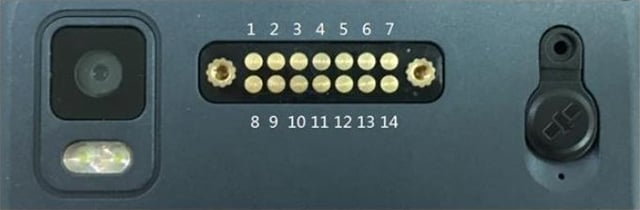
| 1 | GND | Ground PIN | 8 | UART_RX | 3.3V UART RXD |
| 2 | GND | Ground PIN | 9 | UART_TX | 3.3V UART TXD |
| 3 | USB_DM | USB 2.0 bus Data – | 10 | GPIO_1 | 3.3V GPIO 1 |
| 4 | USB_DP | USB 2.0 bus Data + | 11 | GPIO_2 | 3.3V GPIO 2 |
| 5 | USB_ID | USB 2.0 OTG ID PIN | 12 | IRQ | 3.3V External Interrupt PIN |
| 6 | POGO_5V | 5V Power OUT, 1A MAX | 13 | POGO_5V | Same to PIN 6 |
| 7 | POGO_3.3V | 3.3V Power OUT, 1A MAX | 14 | POGO_3.3V | Same to PIN 7 |
Pogo pin path define
Pin5: USB_OTG_ID
Input: externally pull low into OTG mode
Pin6: /sys/class/ext_dev/function/ext_dev_5v_enable
Output: write 1 to open 5V on the back, write 0 to close 5V
Pin7: /sys/class/ext_dev/function/ext_dev_3v3_enable
Output: write 1 to open 3V3 on the back, write 0 to close
Pin10: /sys/class/ext_dev/function/pin10_en
Output: write 1 to pull high, write 0 to pull low
Pin11: /sys/class/ext_dev/function/pin11_en
Output: write 1 to pull high, write 0 to pull low
Pin12: /sys/class/ext_dev/function/irq_state
External interrupt input: 1-external high level; 0-external low level;
Pin8/Pin9 UART: /dev/ttyHSL1
Accessing the UART-port
o access the UART for your device you can use a library that we provide. You can find more information and the library itself here.