August 7, 2024
Press a button
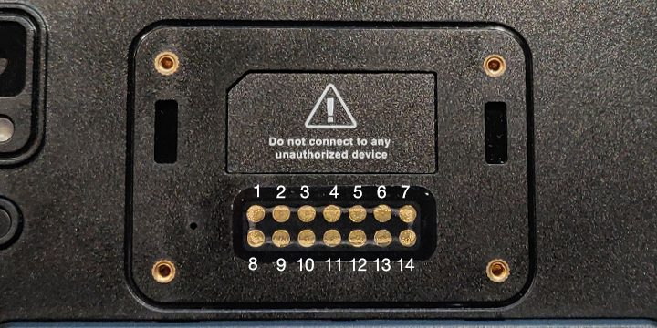
| 1 | GND | Ground PIN | 8 | UART_RX | 1.8V UART RXD |
| 2 | GND | Ground PIN | 9 | UART_TX | 1.8V UART TXD |
| 3 | USB_DM | USB 2.0 bus Data – | 10 | GPIO_1 | 1.8V GPIO 1 |
| 4 | USB_DP | USB 2.0 bus Data + | 11 | GPIO_2 | 1.8V GPIO 2 |
| 5 | USB_ID | USB 2.0 OTG ID PIN | 12 | IRQ | 1.8V External Interrupt PIN |
| 6 | VBUS_5V | 5V/500mA Power OUT (OFF default) |
13 | NA | NA |
| 7 | VBAT | vBat/500mA Power OUT vBat [3.5V – 4.3V] (OFF default) |
14 | NA | NA |
Pin5:USB_ID
Input 0——OTG mode, host mode
Input 1——non-OTG mode, client mode
——————————————————————–
Pin6: VBUS_5V
/sys/class/ext_dev/function/ext_dev_5v_enable
Output 1——Enable 5V output
Output 0——Close 5V output
——————————————————————–
Pin7: VBAT
/sys/class/ext_dev/function/ext_dev_3v3_enable
Output 1——Enable 3.3V output
Output 0——Close 3.3V output
——————————————————————–
Pin10: GPIO_1
/sys/class/ext_dev/function/pin10_en
Output 1——Pull high
Output 0——Pull low
—————————————————————–
Pin11: GPIO_2
/sys/class/ext_dev/function/pin11_en
Output 1——Pull high
Output 0——Pull low
——————————————————————
Pin12: IRQ
You can use below device node to get Pin12 status:
/sys/class/ext_dev/function/irq_state
Read 1——Pin12 is high
Read 0——Pin12 is low
——————————————————————
Pin8-Pin9: UART_RX, UART_TX
/dev/ttyHSL1